Change Language :
dryve motor control system
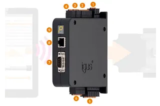
Select, click, control ...
Travels, positions, speeds, operating times - easily defined with the new igus® web-based control system for drylin® E linear systems.
- No software or app installation required, quick start-up
- Control system possible via smart phone (browser), tablet or laptop
- Simple and intuitive user interface, control system set up in minutes
- Compatible with numerous industrial controllers (e.g. the Siemens S7 / Beckhoff).
- For DC, EC and stepper motors
- Cost-effective
All relevant documents - flyers and technical data, the latest firmware, operating instructions, CANopen Electronic Data Sheet, 2D and 3D drawings - can be found in the shop on the page of the corresponding product under downloads.
Test dryve motor control system
You can use the intuitive browser interface to set the travel mode, positions, accelerations, speed and pause times of your linear axis in just a few minutes without any prior knowledge.
Test the user interface of the motor controller here using a simulated linear axis. Just as in this simulation, your input is transferred directly when you use the real control system. There is no need for separate transfer.
It's that easy: Under "Drive profiles", you can configure up to eight lines and apply the control parameters to the linear axis. Use the Mode field to set the zero point with HOM or the absolute position for the movement on the linear axis with ABS. Select the target by entering the position on the axis or by using the teach function. Enter values for acceleration, speed and deceleration and, if necessary, a pause time. Under "Next record" you specify the number of the next travel profile.
Further details
Logic and load supply are separate to allow for safety shutdowns.
The logic supply has 12V to 24V and the load supply 12V to 48V.
Movements can be selected, started and stopped at the 10 predefined inputs. With two limit switches and an enable input, the motor control system can also perform safety functions.
Information from the motor control system can be called up at the 5 predefined outputs. The motor control system reports whether it is ready or is currently executing a movement, whether it is referenced or whether warnings or errors are present.
Two analogue inputs can be used to read in absolute position information of a linear axis, for example, or to specify speeds or positions. Using an "electronic hand wheel", a linear axis can be moved without changing the parameters.
DC, 3-phase EC and 2-phase stepper motors can be connected to the motor connection. A motor brake connection is also integrated in this connector.
A rotary encoder is required to enable optimum motor control and specification of an exact position. The motor control system is designed for many different types of rotary encoder with a voltage supply of 5 V.
The control system in detail
Videos
Technical data
Nominal voltage logic supply
12 - 24 VDC
Nominal voltage load supply
12-48VDC
Motor types
2-phase stepper motor bipolar (ST), direct current motor (DC), electronically commutated motor (EC)
Continuous motor current
7A
Peak motor current
ST: 10A, DC: 14A, EC: 21A max. 2 sec depending on frequency of movement
Load power output
max. 340W continuous
Output current digital outputs
max. 200mA per output
Holding brake
24V DC/1A
Angular encoder
Hall sensor (two or three poles), encoder (line driver RS422 or single-ended)
analogue feedback via analogue inputs
Digital inputs
10 digital inputs, predefined function, selection NPN or PNP, built-in pull-down (PNP) and pull-up (NPN) resistors, short-circuit-proof, galvanically separated, 5 - 24 VDC (external)
Digital outputs
5 digital outputs, function predefined, PNP, built-in pull-down resistors, short-circuit-proof, galvanically separated, 5 - 24 VDC (external)
Analogue inputs
2 analogue inputs, ±10 VDC signal (12 bit), 0-10 VDC signal (11 bit), 10 VDC power supply
Interfaces
CANopen (DS 402), Modbus TCP as gateway (CiA 309), Ethernet, bit coding, cycle/direction
Operating modes
Open loop with/without position monitoring, closed loop
Travel modes
Binary: 32 travel positions Tip/Teach: eight travel positions in combination with external jog mode
Step/direction: external stipulation of set point
CE mark according to electromagnetic compatibility guideline
EN 61000-6-2:2005, EN 61000-6-3:2007
Ambient temperature
-20 °C to +45 °C
Relative humidity
≤ 90%, non-condensing
Maximum temperature of the power unit
100°C
Bearing temperature
-40°C to +60°C
Protection class
IP 30
Protective functions
Power unit temperature monitoring, current monitoring, undervoltage and overvoltage protection, contouring error detection, rotary encoder control
Fastening
Screw assembly, top-hat (DIN) rail installation
D x W x H in mm (incl. connectors and mounting elements)
124 x 31 x 139
Consulting
I look forward to answering your questions

Shipping and consultation
In person:
Monday to Friday from 8:30am - 5.30 pm.
Online:
24h
WhatsApp-Service:
Monday - Friday: 8:30am - 5.30 pm.